





Tooling is the least transparent line on an EPP quotation. Buyers routinely receive a single number — sometimes with a cavity count beside it, often without — and no way to tell whether they are looking at a robust tool built for a decade of production or a lightweight development tool that will be re-cut within two years. Because the tool is paid once and the part is paid forever, that opacity is expensive: a cheap tool that adds forty seconds to every cycle can cost more over a three-year programme than the tool itself.
This article is written for the person who has to approve that line item. It explains how an EPP tool physically works, where aluminium and steel genuinely differ, which design features inflate tooling cost and which do not, what drives cycle time, what should be in a T1 report, and how to amortise the investment without misleading yourself. It also lists the situations in which a mould is the wrong answer — because for prototypes and low volumes it frequently is.
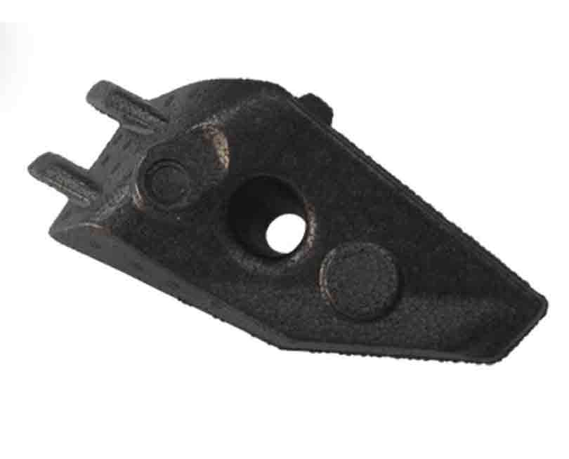
The parts where this matters most are the ones that carry load or absorb energy: bumper core and energy-absorber liners, trunk compartment elements, seat cushions and battery-pack structures. In those applications the tool does not merely shape the part — it determines where the ribs run, how the section collapses under impact and whether the energy absorption in the EV battery pack is repeatable from the first shot to the hundred-thousandth.
EPP is not injection moulded: what the tool actually does
Expanded polypropylene starts as solid resin beads a few millimetres across, each carrying a blowing agent. The beads are pre-expanded with steam to a target bulk density, aged so that the blowing agent redistributes and the cell walls regain stiffness, and then blown into a closed mould. Inside the mould they are heated again with steam; the residual blowing agent expands, the beads soften, press against each other and fuse at their contact faces. The part is then cooled until it is stiff enough to be ejected without distorting.
That process explains the shape of the tool. There is no screw, no melt cushion and no injection pressure in the ordinary sense. Instead, the cavity and core are relatively thin shells — often machined from aluminium billet or cast aluminium — and behind each shell sits a steam chamber. Steam is admitted through the chamber wall, passes through vent slots and core vents into the bead bed, and is exhausted the same way. Cooling water then runs through the same chamber. The tool is therefore a heat exchanger first and a shaping device second, and its walls are kept thin on purpose so that heat can move in and out quickly.
The rest of the tool follows: fill guns that inject beads pneumatically and act as seals afterwards, ejector pins or an ejector plate, sealing faces around the parting line that must hold steam without leaking, and often separate steam circuits for the cavity and the core so that the two sides can be balanced. Where a part has deep ribs or a thick section, the tool may carry local steam plungers that push steam directly into that region, because steam will otherwise take the path of least resistance and leave the thick area under-fused.
Aluminium versus steel: where each one actually belongs
The comparison is often framed as a durability contest, which misses the point. Aluminium is not chosen for EPP tooling because it is cheaper — although it usually is — but because its thermal conductivity is roughly three to four times that of tool steel. In a process where every cycle consists of heating a mass of metal and beads and then removing that heat again, thermal conductivity translates directly into seconds per shot, and seconds per shot translate into capacity.
Steel earns its place in specific locations rather than as a whole-tool material: at parting lines that take repeated mechanical abuse, around fill guns and ejector seats, in thin blades and core pins that would deform in aluminium, on textured surfaces that must hold detail over millions of shots, and in any area where an abrasive or filled grade of bead will erode the surface. A well-built tool is often a hybrid — aluminium cavity and core shells with steel inserts at exactly those points.
| Criterion | Aluminium tool | Steel tool |
|---|---|---|
| Thermal conductivity | High — heats and cools fast | Roughly a third to a quarter as fast |
| Typical effect on cycle | Baseline | Longer heating and cooling phases |
| Tool mass and handling | Light, easier to change and store | Heavy, needs more crane capacity |
| Machining time | Fast; complex geometry cut quickly | Slower, especially in hardened grades |
| Typical production role | Production tool for packaging and automotive volumes | Long-life tool, fine detail, wear-critical inserts |
| Repair | Local weld or insert; usually quick | Weld repair needs stress relief and re-machining |
| Wear resistance | Adequate for standard EPP bead | Better where bead is abrasive or filled |
| Best fit | Most moulded EPP parts, including high-volume programmes | Very long programmes, tight-detail parts, abrasive grades |
Two practical consequences follow. First, do not accept “steel” as an automatic proxy for quality; a heavy steel tool that doubles cycle time can be a worse commercial decision than a well-maintained aluminium tool that lasts a decade. Second, do ask where the steel is: a supplier who can point to the specific inserts and explain why they are there understands the process, and one who cannot is probably quoting from a template.
Tool life itself is usually quoted as a shot count, but the number that matters is usable shots. Aluminium EPP tools commonly reach several hundred thousand shots and, with scheduled vent cleaning and surface maintenance, can go considerably further; the limiting factor is rarely a catastrophic failure and almost always progressive loss of surface finish, blocked vents or damaged sealing faces. If your programme needs a number, ask for the maintenance interval that supports it, not just the headline figure.
Cavity count and layout: the first decision that sets the part price
Cavity count is where tooling cost and part cost pull in opposite directions. More cavities mean a larger, heavier, more expensive tool and a bigger machine, but they divide the fixed cost of every cycle across more parts. The optimum depends on annual volume, part size, how much of the cycle is dominated by heating and cooling rather than by handling, and whether the part is large enough that a second cavity simply will not fit a sensible steam chest.
Layout matters as much as count. Cavities must be balanced so that each one fills at the same rate, otherwise some parts come out heavier and better fused than others and the whole tool has to be run to the slowest cavity. Fill guns should reach the far end of each cavity, not just its centre, and the steam circuit should let each cavity be valved independently if the parts differ in wall thickness. These are cheap decisions at the drawing stage and expensive ones afterwards.
Which design features add tooling cost — and which do not
Buyers often assume that geometric complexity is what makes a tool expensive. In EPP tooling the bigger drivers are usually the features that interfere with steam flow, sealing or ejection, because those force extra tooling elements rather than just more machining time.
- Undercuts and side actions. Anything that cannot be ejected along the main opening direction needs a slider, lifter or collapsing core. Each one is an extra mechanism that must seal against steam, and each one adds cost, maintenance and a potential leak path.
- Non-uniform wall thickness. Thick sections need extra steam, extra cooling and sometimes local plungers; thin sections risk incomplete fill. A part that holds a consistent wall is dramatically easier to tool than one that does not, even if the uniform version looks more complicated on paper.
- Deep, narrow ribs. Ribs thinner than the bead can reliably fill will not form properly no matter how good the tool is. Deep ribs also need ejector provision that does not mark the visible face.
- Fine surface texture and gloss. Texture has to be cut or etched into the cavity and then maintained; a polished cosmetic surface is more expensive to produce and to keep than a standard moulded skin, and it shows every flow mark.
- Moulded-in inserts and labels. Holding a metal insert in position against steam pressure and bead flow requires locating pins and often a dedicated load/unload step, which changes both tool cost and cycle time.
- Tight dimensional tolerance. Tolerance is partly a tooling question and partly a process-control question; asking for a band tighter than the material can hold repeatably buys inspection cost rather than capability.
- Engraved logos and date stamps. Usually inexpensive — a simple insert or engraved patch — and worth doing at the tooling stage rather than as a secondary operation.
- Simple radii, draft and generous fillets. Effectively free. They improve ejection and part strength at no tooling cost, which is why they belong in the first drawing revision.
What actually determines cycle time
A cycle time quoted as a single number is close to meaningless, because the same part can be run fast with poor fusion or slow with excellent fusion, and the difference is a process choice as much as a tool property. What a buyer should ask for is the moulding window: the range of steam pressures, times and cooling settings within which the part meets its density, dimension and fusion requirements, and where in that window the quoted cycle sits.
| Phase | What happens | Main drivers |
|---|---|---|
| Closing and sealing | Tool closes, fill guns seat, seals engage | Tool rigidity, seal condition |
| Filling | Beads blown in pneumatically until the cavity is full | Bead flowability, fill-gun position, venting, crack pressure |
| Steam heating | Steam displaces air, beads expand and fuse | Wall thickness, density, steam quality, tool thermal mass |
| Holding | Pressure held while fusion completes through the section | Section thickness, bead grade, target fusion level |
| Vacuum and water cooling | Steam exhausted, vacuum applied, water circulated | Water temperature, circuit design, part thickness |
| Pressure release and stabilisation | Internal pressure equalises before opening | Density, wall thickness, part size |
| Ejection and handling | Part removed, tool closed again | Ejector design, automation, operator handling |
Four variables dominate in practice. Wall thickness is the most important, because heat has to travel through the bead bed and back out again; doubling a section lengthens both the heating and the cooling phase, and no amount of steam pressure removes that physics. Density comes next: a denser part contains more polymer per unit volume, needs more heat to fuse and holds more heat to remove. Steam quality — how dry and how consistently pressurised the supply is — decides whether the quoted cycle is achievable in July as well as in January. And tool thermal mass decides how much of each cycle is spent heating and cooling metal rather than product, which is precisely why thin aluminium shells outperform heavy steel blocks on cycle even though they lose on wear.
T1 samples: what a first-article package should contain
T1 is the first trial on a new tool, usually run in the supplier's own plant before any production commitment. It is not a beauty contest for the sample in the photograph; it is the moment when the tool's real behaviour becomes visible. Treat the T1 report as the acceptance document for the tooling investment, and do not release final payment against a photograph.
- Dimensional report against the drawing, on parts measured after stabilisation — not straight off the tool. Moulded EPP continues to shrink and relax for hours after ejection, so dimensions taken immediately are optimistic and will not repeat in production.
- Weight and density per cavity, compared with the target. Weight is the fastest indicator of fill consistency, and a spread between cavities usually points to an unbalanced layout or unequal venting.
- Fusion evidence, not a verbal assurance. A peel or knife test on a deliberately broken section, photographed, plus tensile testing to an agreed method if the application is structural. Under-fusion looks fine and fails in service.
- Surface and appearance report: flow marks, knit lines, steam marks, sink, ejection marks and any flash at the parting line, with photographs taken under consistent lighting.
- Warpage measurement, ideally on a flat reference face or between defined datum points, with the part supported as it would be in use rather than clamped flat.
- The moulding window: at least three settings — low, nominal and high steam — with the resulting part weight, key dimensions and fusion result for each, so you can see how much margin exists before quality falls away.
- Shrinkage and tool compensation record: what shrinkage factor was applied, what was measured, and what correction is planned for T2. This is how you tell whether the tool was cut from experience or from a guess.
- Process sheet: fill pressure and time, steam pressures per circuit, hold time, cooling time and temperatures, vacuum level, cycle time, and the bead grade and pre-expansion density actually used.
- Open issues list with owners and dates. A T1 with no open issues is either a remarkably mature tool or a report that has been written to look that way.
One practical caution about dimensions: because moulded EPP moves after ejection, the measurement timing must be written into the acceptance criteria. “Measured 24 hours after ejection, at 23 °C, part unsupported” is a specification; “measured after moulding” is an argument waiting to happen. The same stabilisation logic underpins the tolerance discussion in our guide to EPP dimensional tolerances and quality control.
It is also worth asking what changes between T1 and T2. A tool that needs no correction at all is rare; a supplier who arrives at T1 with a documented list of expected corrections — a shrinkage adjustment here, an ejector repositioned there — is demonstrating that they have moulded this family of parts before.
Tooling cost: what you are actually paying for
Rather than publish numbers that would be wrong for your part, it is more useful to understand the structure. In an EPP tool quotation, cost concentrates in four places: the cavity and core shells and their steam chests; the mechanism — ejectors, sliders, fill guns, seals; the trial rounds including the moulding time and the engineer's time; and the finishing, texturing and any inserts. Part size drives the first, part complexity drives the second and fourth, and the programme's quality expectations drive the third.
| Cost element | Driven by | Where buyers overspend |
|---|---|---|
| Cavity and core shells | Part projected area, depth, wall uniformity | Choosing a cavity count before volumes are confirmed |
| Steam chest and circuits | Tool size, number of independent zones | Paying for zoning the part does not need |
| Ejector and mechanism | Draft, undercuts, ejection area | Late design changes after cutting |
| Fill system | Cavity layout, bead grade | Adding cavities to fix a fill problem |
| Inserts and wear protection | Bead abrasiveness, detail required | Specifying steel everywhere |
| Trial rounds | Number of T rounds, travel, samples shipped | Skipping T rounds to save time |
| Finishing and texture | Cosmetic class, logo, gloss | Cosmetic specs with no functional reason |
Amortisation is simple arithmetic that is often done dishonestly. Tooling cost per part equals tool cost divided by the number of parts actually expected over the tool's life — not the number in the business case. If a tool costs 18,000 in your currency and the realistic lifetime volume is 120,000 parts, the tooling contribution is 0.15 per part. If the programme delivers only 40,000 parts, the same tool contributes 0.45 per part, and a quotation built on the optimistic number will look 0.30 too cheap on every unit.
Three commercial points are worth negotiating explicitly. First, payment milestones tied to evidence — design freeze, tool completion, T1 report accepted, production trial accepted — rather than a deposit and a balance on shipment. Second, how many trial rounds are included, because the second and third rounds are where most tools actually become production-ready. Third, what happens to the tool at the end of the programme: who stores it, who pays for maintenance, and on what terms it can be transferred.
Ownership, maintenance and tool transfer
Tooling is often the buyer's largest single asset in the relationship, and it is frequently the least documented. Whether the tool is paid for outright or amortised into part price, establish in writing who owns it, where it is held, and what documentation accompanies it. A tool without its process sheet is only half an asset: the next moulder can reproduce the geometry but not necessarily the result.
- Ownership and location stated in the supply agreement, including what happens if the relationship ends and who bears transport.
- Tool history file: material certificates for cavity and core, machining and correction records, every trial round with its settings, and a maintenance log.
- Maintenance schedule: vent and core-vent cleaning at a defined interval, seal inspection, surface inspection, and re-texturing when finish degrades. Most “tool failures” are missed maintenance, not metal fatigue.
- Spare parts list: fill guns, seals, ejector pins and any steel inserts, ideally with one set held in stock.
- Transfer package: 3D model as built, 2D drawing with the shrinkage factor applied, process sheet, pre-expansion and ageing procedure, and the fusion acceptance criterion.
- Storage conditions: dry, supported, parting faces protected. An aluminium tool stored face-down on a concrete floor will corrode and lose its sealing faces.
If you are moving a tool between plants, plan the transfer around a trial rather than a shipment. Steam supply, water temperature and bead source all change the result, and the receiving plant needs a baseline to compare against. A tool that produced perfect parts in one factory can produce under-fused parts in another without anything being wrong with the tool.
Design for moulding: a pre-drawing checklist
Most tooling problems are created before the tool exists. The items below cost nothing to fix at drawing stage and a great deal afterwards, which is why they belong in the first design review with the moulder rather than in a change request after T1.
- Uniform wall thickness wherever the function allows, with transitions tapered rather than stepped.
- Draft of at least one to two degrees on every face parallel to the opening direction; more on textured surfaces.
- Radii and fillets at internal corners — they reduce stress concentration and help bead flow.
- No rib thinner than the bead can fill; consolidate thin ribs into fewer, thicker ones.
- Ejection points placed on non-cosmetic faces, with enough area to avoid marking.
- Undercuts eliminated or converted into a snap feature that can be stripped, if the material allows.
- Moulded-in identification — part number, cavity number, material and date — designed in, not added later.
- Tolerance bands agreed per dimension, with a realistic general tolerance and tighter values only where the assembly genuinely needs them.
- Assembly interfaces checked against the as-moulded condition, not the CAD nominal.
- A stated density and bead grade, because neither geometry nor tolerance means much without them.
The density and bead grade question deserves its own conversation. A tool cut for one density can usually mould a range around it, but the shrinkage compensation is only optimised for the design point, and fusion behaviour changes with density. If your programme spans two densities, say so before the tool is cut — the guide to choosing EPP foam density explains how density moves both mechanics and dimensions, and the same logic applies to tooling.
When a mould is the wrong investment
A tool is a commitment to a geometry, a density and a volume. When any of those three is still moving, the honest answer is usually not to cut steel — or aluminium.
- Very low annual volume. Below a few hundred pieces a year, the tooling contribution per part can exceed the part's material cost. Machined or cut-and-bonded EPP block, or a thermoformed insert, is often the better commercial answer for the first year — the same reasoning that separates board materials from moulded parts in our EPP and XPS comparison.
- Design still in flux. If the CAD is likely to change in the next quarter, prototype with cut foam and validate the fit before committing to a cavity.
- Wall sections below what the bead can fill. Thin-wall moulding exists, but it needs fine bead, high pressure and a tool built specifically for it — and it is a different cost class.
- Tolerances tighter than the process holds. If the real requirement is ±0.2 mm on a large moulded part, the correct solution is usually a design change or a secondary machining step, not a more expensive tool.
- One-off or exhibition parts. Cutting a tool to make twelve parts is a decision that rarely survives the finance review.
None of this argues against tooling — for any programme with a stable design and a real volume, a mould is the cheapest way to make a complex EPP part, and the only way to get repeatability. It argues for sequencing: validate the design cheaply, then commit to the tool once the geometry has stopped moving.
How to brief a tooling supplier
A briefing pack that gets a useful quotation contains six things: the 3D model and a 2D drawing with critical dimensions flagged; the target density and bead grade; the annual and lifetime volumes, honestly estimated; the application and its mechanical or thermal requirements; the cosmetic standard, with photographs of an acceptable surface if one exists; and the logistics constraints — machine size, container loading, and whether the tool will ever need to move.
With that pack, a competent supplier can quote cavity count, tool material, trial rounds and lead time with reasons attached. Without it, you will get a number and a lead time, and you will spend the first trial round discovering which assumptions were made on your behalf. Our custom EPP design and production process runs from drawing review through tooling and first article, the customisation centre shows the range of parts the same approach produces, and the plant and capability overview lists the machine sizes that constrain how large a tool — and therefore how large a part — is practical.
Frequently asked questions
How long does EPP tooling take from drawing to T1?
Is an aluminium EPP mould durable enough for series production?
What is a T1 sample and why does it matter?
Why do my dimensions only settle a day after moulding?
Can one tool mould different densities?
Who owns the tool, and can I move it to another moulder?
What draft angle does an EPP part need?
If you are at the stage of comparing tooling quotations, the most useful next step is not another price — it is a drawing review. Send the 3D model, the target density and the annual volume, and ask for the cavity count, the tool material split, the number of trial rounds and the maintenance interval in writing. That set of answers tells you more about the supplier than the number at the bottom of the page.










 East side of Jiaoping Road, Madian Industrial Park, Jiaozhou City, Qingdao City, Shandong Province
 +86-
 market@qd-smr.com

 East side of Jiaoping Road, Madian Industrial Park, Jiaozhou City, Qingdao City, Shandong Province
 +86-15588637956
 market@qd-smr.com